Manual transmission systems rely on precise shifter mechanisms for gear selection, offering drivers direct control․ Understanding the assembly is crucial for maintenance and repair․
This guide details the parts and processes involved, referencing diagrams and catalogs for effective troubleshooting and operation of your transmission․
Overview of Manual Transmissions
Manual transmissions, a cornerstone of automotive engineering, fundamentally differ from automatic systems by requiring the driver to select gears using a shifter․ This direct mechanical linkage connects the shift lever to internal components within the transmission itself․
Unlike automatic transmissions that utilize hydraulic pressure and planetary gearsets, manual systems employ a series of gears that are physically engaged by the driver․ The core principle involves disconnecting the engine from the wheels momentarily, allowing for selection of a different gear ratio․ This process is facilitated by the clutch pedal, which disengages the engine’s power․
Understanding this basic operation is key to appreciating the role of the shifter assembly, which translates driver input into precise gear changes․ Proper function ensures efficient power delivery and vehicle control, referencing diagrams for clarity․
Purpose of the Shifter Assembly
The shifter assembly serves as the critical interface between the driver and the manual transmission, enabling precise gear selection․ Its primary function is to accurately transfer the driver’s input – movement of the shift lever – into corresponding actions within the transmission’s internal gear selection mechanisms․
This is achieved through a complex network of shift linkage, whether direct or cable-operated, ensuring smooth and reliable engagement of the desired gear․ A properly functioning assembly is vital for optimal vehicle performance, preventing issues like difficulty shifting or a loose feel․
Furthermore, the shifter often incorporates a reverse lockout mechanism for safety, and utilizes components like a shift knob and shift boot for user comfort and control, as detailed in parts catalogs․

Key Components of a Manual Shifter Assembly
Essential parts include the shift lever, shift linkage (cables or direct connections), and internal transmission components like shift forks and selector rods․
Shift Lever (Stick Shift)
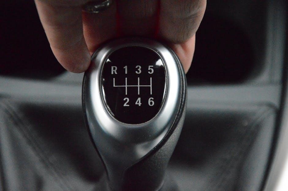
The shift lever, commonly known as the stick shift, is the driver’s primary interface for selecting gears within a manual transmission․ It’s typically a metal rod extending into the vehicle’s cabin, topped with a shift knob for ergonomic grip and operation․
Its design varies, featuring different lengths, bends, and patterns to accommodate specific transmission layouts and vehicle designs․ The lever’s movement directly translates into commands sent to the shift linkage, initiating the gear change process․ Quality shift levers are robust, minimizing play and ensuring precise engagement․
Proper maintenance involves checking for looseness and ensuring smooth, defined movement․ A worn or damaged shift lever can lead to imprecise shifting and difficulty selecting gears, impacting driving experience and safety․
Shift Linkage
The shift linkage is the crucial system connecting the shift lever to the transmission, translating driver input into gear changes․ It comprises rods, cables, or a combination of both, meticulously engineered for precise movement․ Two primary types exist: direct and cable-operated systems․
Direct linkage utilizes rigid rods for a solid, responsive feel, common in older vehicles․ Cable-operated systems employ flexible cables, offering design flexibility and reduced vibration transfer․ Regardless of type, proper alignment and secure connections are vital․
Worn bushings or loose connections within the shift linkage result in sloppy shifting, imprecise gear selection, and potential damage to transmission components․ Regular inspection and maintenance are essential for optimal performance․
Direct Linkage Systems
Direct linkage systems, prevalent in older manual transmissions, employ a series of rigid rods directly connecting the shift lever to the transmission’s internal shifting mechanisms․ This configuration provides a very direct and tactile feel, favored by enthusiasts for its precision and responsiveness․
These systems typically utilize pivot points and ball joints, allowing for movement in multiple planes․ Maintaining proper alignment of these components is critical; even slight deviations can cause binding or difficulty shifting․
While robust, direct linkage is susceptible to wear at the pivot points, requiring periodic lubrication and bushing replacement․ The simplicity of the design, however, makes diagnosis and repair relatively straightforward․
Cable-Operated Systems
Cable-operated systems represent a more modern approach to manual transmission shifting, utilizing steel cables to transmit movement from the shift lever to the transmission․ This design offers greater flexibility in shifter placement, allowing for more ergonomic cabin layouts․
These systems consist of a shift lever connected to cables that run through a protective sheath․ Adjustments are crucial to ensure precise gear engagement․ Cable stretch and corrosion are common issues, leading to sloppy shifting or difficulty selecting gears․
Regular inspection and lubrication of the cables are essential for smooth operation․ Replacement cables are readily available and relatively inexpensive, making maintenance straightforward․
Transmission Internal Components Involved
Within the transmission itself, several key components interact with the shifter assembly to facilitate gear changes․ Shift forks are crucial, moving synchronizer sleeves to engage the desired gear․ These forks are directly actuated by selector rods, which receive input from the shift linkage․
Selector rods translate the cable or direct linkage movement into a linear motion, precisely positioning the shift forks․ Synchronizer sleeves ensure smooth, clash-free gear engagement by matching the speeds of the gears before they lock․ Proper lubrication and alignment of these internal parts are vital․
Wear on these components can lead to difficulty shifting or internal transmission damage․
Shift Forks
Shift forks are integral to the manual transmission, acting as the direct interface between the selector rods and the synchronizer sleeves․ Typically constructed from hardened steel, they withstand significant force during gear engagement; Their design features two prongs that slide into grooves on the synchronizer hub, pushing it along the main shaft․
Precise alignment and smooth movement of the shift forks are essential for effortless gear changes․ Bent or worn shift forks can cause difficulty selecting gears, grinding noises, or even complete gear lockout․ Regular inspection for wear and damage is recommended during transmission service․
Proper lubrication minimizes friction and extends their lifespan․
Selector Rods
Selector rods, also known as shift rods, are crucial components linking the shift linkage to the shift forks within the manual transmission․ These rods translate the driver’s gear selection into movement of the forks, engaging the desired gear․ They are typically long, slender metal rods with precisely machined ends to connect securely․

Proper alignment and free movement of the selector rods are vital for smooth shifting․ Wear or bending can lead to imprecise gear engagement, causing grinding or difficulty selecting gears․ Regular inspection and lubrication are essential maintenance steps․
Correct rod positioning is critical during reassembly after transmission work․

Detailed Parts Breakdown
Detailed examination of each shifter component – from the shift knob to the reverse lockout – reveals the intricacies of the manual transmission system․
Shift Knob
The shift knob, often overlooked, is the driver’s primary interface with the manual transmission․ It’s more than just a cosmetic element; its shape, weight, and material significantly impact the shifting experience․ Various materials like aluminum, plastic, or even wood are commonly used, each offering a different feel․
Beyond aesthetics, the shift knob’s design influences leverage and control․ Aftermarket options frequently provide enhanced grip and a more precise feel, improving driver confidence․ Threaded designs allow for easy installation and removal, facilitating customization․
Properly securing the shift knob is vital; a loose knob can hinder smooth gear changes and even pose a safety risk․ Regular inspection ensures it remains firmly attached to the shift lever, maintaining optimal functionality and driver comfort․
Shift Boot
The shift boot is a crucial, often underestimated component of the manual transmission shifter assembly․ Primarily, it serves to seal the opening between the shift lever and the vehicle’s interior, preventing the ingress of dust, dirt, and moisture․ This protection safeguards the internal transmission components from contamination․
Beyond its functional role, the shift boot contributes to the vehicle’s interior aesthetics․ Available in various materials like leather, vinyl, or fabric, it complements the cabin’s design․ A damaged or torn shift boot not only looks unsightly but also compromises its sealing function․
Replacing a worn shift boot is a relatively simple task, restoring both the interior’s appearance and the transmission’s protection․
Console Plate/Bezel
The console plate, often referred to as a bezel, is the decorative and functional trim piece surrounding the manual transmission shifter․ It securely mounts the shift lever to the center console, providing a finished and aesthetically pleasing appearance within the vehicle’s interior․
Beyond aesthetics, the console plate often incorporates features like the reverse lockout mechanism or provides a mounting point for the shift knob․ Constructed from materials like plastic or metal, it’s designed to withstand regular use and prevent unwanted movement of the shifter․
Damage to the console plate can occur, requiring replacement to maintain both functionality and the vehicle’s interior quality․
Reverse Lockout Mechanism
The reverse lockout mechanism is a critical safety feature within a manual transmission shifter assembly․ It prevents accidental engagement of reverse gear while the vehicle is moving forward, safeguarding the transmission and preventing potential damage or loss of control․
Typically, this mechanism requires the driver to depress the shift lever fully or lift a collar before engaging reverse․ Various designs exist, including mechanical linkages and solenoid-based systems․ Proper functionality is essential for safe operation․
Failure of the reverse lockout can lead to unintended reverse engagement, necessitating repair or replacement of the associated components within the shifter․
Assembly Process – Step-by-Step
Shifter assembly involves preparing the housing, installing linkage, connecting to the transmission, and precise adjustments for smooth, accurate gear changes․
Preparing the Shifter Housing
Before beginning the assembly, thoroughly inspect the shifter housing for any damage, cracks, or wear․ Clean the interior meticulously, removing old grease, dirt, and debris using a suitable solvent and brushes․
Pay close attention to the mounting points and ensure they are free from corrosion or obstructions․ Verify the condition of any bushings or grommets within the housing, replacing them if necessary to ensure smooth shift linkage movement․
Lubricate the internal surfaces of the housing with a light coating of grease specifically designed for manual transmissions․ This will help reduce friction and prevent premature wear․ Confirm the reverse lockout mechanism functions correctly before proceeding․
Installing the Shift Linkage
Carefully install the shift linkage components into the prepared shifter housing, ensuring proper alignment with the transmission․ Connect the shift lever to the linkage, verifying free movement through all gear positions․
For cable-operated systems, route the cables correctly, avoiding any sharp bends or obstructions․ Securely attach the cable ends to the transmission and adjust the cable tension according to the manufacturer’s specifications․
With direct linkage, confirm all connections are tight and properly seated․ Lubricate all pivot points and joints with grease․ Double-check for any binding or interference before proceeding to the next step․
Connecting to the Transmission
Carefully align the shift linkage with the corresponding engagement points on the transmission․ Securely attach the linkage, ensuring a firm and stable connection․ Verify that the shift forks move freely when the shift lever is operated․
For cable-operated systems, connect the cable to the transmission’s shift mechanism, confirming proper seating and retention․ Inspect the cable routing to prevent interference with other components․
Double-check all connections for tightness and security․ A loose connection can lead to inaccurate gear selection or even complete transmission failure․ Lubricate all contact surfaces to ensure smooth operation․
Adjusting Shift Linkage for Proper Operation
Precise adjustment of the shift linkage is vital for accurate gear engagement․ Begin by verifying neutral position alignment; the transmission should be in neutral when the shifter is centered․
Adjust linkage rod ends or cable tension to eliminate binding or looseness․ Ensure each gear position corresponds correctly with the shift lever’s movement․ Use a diagram as a reference for proper positioning․
Test each gear thoroughly, checking for smooth and positive engagement․ Fine-tune adjustments until all gears select without resistance․ Incorrect adjustment can cause difficulty shifting or damage to the transmission․

Troubleshooting Common Issues
Common problems include difficult shifting, a loose feel, or binding․ Inspect linkage, bushings, and internal transmission components for wear or damage to diagnose issues․
Difficulty Shifting into Gear
Difficulty shifting often stems from issues within the shift linkage or the transmission itself․ Begin by inspecting the linkage for looseness, wear, or damage to the bushings․ A worn or improperly adjusted linkage can prevent full engagement of the shift forks․
Internally, problems with the shift forks, selector rods, or synchronizers can cause difficulty․ Check for bent shift forks or binding selector rods․ Worn synchronizers may require a transmission rebuild․
Also, ensure the clutch is fully disengaging; a partially engaged clutch makes smooth shifting impossible․ Consult diagrams to verify correct linkage routing and component placement․ Proper lubrication of linkage points is also essential for smooth operation․
Loose or Sloppy Shifter Feel
A loose or “sloppy” shifter feel typically indicates worn components within the shift linkage․ The most common culprits are worn bushings in the shift linkage, allowing excessive play․ Inspect these bushings carefully and replace them as needed, referencing a parts catalog for correct replacements․
Additionally, check the mounting points of the shifter itself and the transmission for any looseness․ Tighten any loose bolts or brackets․ Internal wear within the transmission, such as worn shift forks, can also contribute to a vague feel․
Proper adjustment of the shift linkage is crucial; consult diagrams for correct settings․ Lubricating the linkage points can temporarily improve feel, but addressing worn parts is the long-term solution․
Shifter Binding or Sticking
Shifter binding or sticking often stems from insufficient lubrication within the shift linkage or internal transmission components․ Begin by thoroughly lubricating all pivot points in the linkage with a suitable grease, ensuring full range of motion․ Inspect the shift cable (if equipped) for kinks or damage․
Internal binding can indicate worn shift forks or selector rods․ A diagram of the transmission internals will aid in identifying these parts․ Corrosion can also contribute to sticking; cleaning affected areas may help․
Ensure the reverse lockout mechanism isn’t malfunctioning and impeding movement․ If the issue persists, a transmission rebuild may be necessary to address internal wear or damage․
Diagrams and Schematics
Detailed diagrams illustrate manual transmission layouts, including 4, 5, and 6-speed configurations, aiding in parts identification and assembly understanding․
Typical 4-Speed Shifter Diagram
A standard 4-speed manual transmission shifter diagram reveals a relatively simple, yet effective, linkage system․ The diagram typically showcases the shift lever positioned within the cabin, connected via a direct linkage or cable to the transmission itself․
Key components visible include the shift knob, boot, and console plate, leading down to the shift linkage․ This linkage consists of rods and pivot points, meticulously designed to translate the driver’s input into precise gear selection within the transmission․
The diagram clearly illustrates the pathways for each gear – First, Second, Third, and Fourth – along with Reverse․ Understanding this layout is vital when diagnosing shifting issues or replacing worn parts․ Accessing bushings often requires navigating this arrangement, as noted in online forums discussing manual transmission repairs․
5 & 6-Speed Shifter Layouts
5 and 6-speed manual transmission shifter layouts introduce increased complexity compared to their 4-speed counterparts․ Diagrams reveal more intricate linkage patterns, accommodating the additional gears․ These systems often employ more sophisticated cable routing or direct linkage configurations to ensure accurate gear engagement․
The diagrams highlight the shift pattern – typically an “H” shape – with the added gears requiring precise positioning․ Identifying the correct parts within these layouts is crucial for repair, referencing catalogs and superseding lists is essential․
Troubleshooting can be more challenging due to the increased number of potential failure points․ Online resources emphasize the importance of understanding the specific linkage geometry for proper adjustment and smooth operation of the transmission․

Safety Precautions
Prioritize safety by disconnecting the battery before working on the shifter assembly․ Utilize proper tools and wear safety glasses to prevent injury during disassembly․
Disconnecting the Battery
Before commencing any work on the manual transmission shifter assembly, it is absolutely critical to disconnect the vehicle’s battery․ This precaution minimizes the risk of short circuits and accidental activation of electrical components during the disassembly or reassembly process․
Locate the negative (-) battery terminal and carefully loosen the nut securing the cable clamp․ Once loosened, gently remove the cable from the terminal, ensuring it doesn’t accidentally make contact․ Then, repeat the process for the positive (+) terminal․ Secure the disconnected cables away from the battery posts to prevent accidental reconnection․
This simple step safeguards both you and the vehicle’s electrical system, preventing potential damage and ensuring a safe working environment․ Remember to reconnect the battery in reverse order upon completion․
Proper Tool Usage
Successfully tackling a manual transmission shifter assembly requires utilizing the correct tools․ Employing the wrong tools can lead to damaged components, stripped threads, and ultimately, a frustrating repair experience․ A comprehensive socket set, including metric sizes, is essential․
Additionally, a set of wrenches, both open-end and box-end, will be necessary for various fasteners․ Invest in quality screwdrivers – Phillips and flathead – and consider a breaker bar for stubborn bolts․ Penetrating oil is invaluable for loosening corroded parts․
Always prioritize safety; wear safety glasses and gloves․ Avoid using excessive force, and ensure tools are in good working condition․ Using the right tool for the job is paramount for a successful outcome․

Maintenance and Lubrication
Regularly greasing shift linkage points and inspecting bushings ensures smooth operation․ Lubrication minimizes wear, prevents binding, and maintains precise gear engagement within the assembly․
Greasing Shift Linkage Points
Shift linkage points are critical areas requiring regular lubrication to maintain smooth and precise gear changes․ Applying grease reduces friction between moving parts, preventing stiffness and ensuring effortless shifting․ Utilize a high-quality chassis grease, specifically designed for automotive applications, for optimal performance․
Identify all pivot points and joints within the shift linkage – these include where the shift lever connects to the shift linkage, and where the linkage connects to the transmission․ Use a grease gun with a suitable nozzle to deliver grease directly into these points․ Wipe away any excess grease to prevent contamination․
Frequency depends on driving conditions; more frequent greasing is needed for harsh environments․ Inspect the linkage for wear or damage during lubrication, addressing any issues promptly to avoid further complications within the manual transmission shifter assembly․
Inspecting Bushings and Joints
Regularly inspecting the bushings and joints within the manual transmission shifter assembly is vital for maintaining optimal performance․ These components absorb vibrations and ensure precise movement, but they wear over time, leading to a sloppy shifter feel․ Look for cracks, tears, or excessive play in the rubber or polyurethane bushings․
Pay close attention to the joints where the shift linkage connects to the shift lever and the transmission․ Any looseness indicates bushing degradation․ Worn bushings contribute to imprecise shifts and potential damage to other parts․
Replacement is often necessary when significant wear is detected․ Utilizing a parts catalog to identify the correct bushings is crucial․ Addressing worn bushings restores shifter precision and prevents further issues within the transmission․

Parts Catalogs and Superseding Lists
Parts catalogs are essential for identifying correct manual transmission shifter assembly components․ Superseding lists detail updated parts, ensuring compatibility and availability․
Locating Replacement Parts
Finding replacement parts for your manual transmission shifter assembly requires utilizing several resources․ Begin with a detailed parts catalog specific to your vehicle’s make and model year․ These catalogs often include exploded views and precise part numbers, simplifying identification․
Online retailers specializing in automotive components are also valuable․ Cross-reference part numbers to ensure accuracy․ Dealership parts departments offer genuine OEM (Original Equipment Manufacturer) parts, guaranteeing fit and quality, though often at a higher cost․
Remember to consult superseding lists, as parts may have been updated or discontinued․ These lists indicate compatible replacements․ When sourcing parts, consider the condition – new, remanufactured, or used – balancing cost with reliability․ Always verify return policies before purchasing․
Understanding Superseding Information
Superseding information is critical when sourcing manual transmission shifter assembly parts․ Manufacturers frequently update parts due to improvements, material changes, or discontinuation of original components․ A superseding part replaces the original, offering equivalent or enhanced functionality․
Catalogs and online databases will indicate if a part has been superseded, listing the new part number․ Ignoring this can lead to incorrect parts orders and compatibility issues․ Always check for the latest superseding data before purchasing․
Understanding these updates ensures you obtain the correct component for your transmission․ Utilizing transmission-specific superseding lists is vital for accurate repairs and maintaining the assembly’s integrity․ Proper identification avoids delays and ensures a successful repair․